1. Product introduction
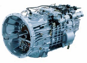
The 16TA transmission (see Figure 1) is a high torque 16-speed transmission. The transmission adopts a main and auxiliary box structure, and the auxiliary box is divided into a front sub-box and a rear sub-box, wherein the front sub-box and the clutch housing are integrated. The main box is 4 speeds, and the front and rear sub-boxes have high and low speeds. The first and second speed synchronizers are double cone synchronizers, the third and fourth speed synchronizers are single cone synchronizers, and the reverse gear is gear sleeve shifting. The housing structure is a barrel structure.

figure 1
2. Assembly assembly difficulty analysis
Due to the large number of gears and complicated structure of the 16TA transmission, and the housing is a barrel structure, the connection mode is horizontal, which is different from the previous transmission structure. Among them, the assembly of the shaft assembly, the adjustment of the intermediate shaft bearing clearance, the disassembly of the auxiliary box bearing and the two-shaft rear bearing of the main box, the disassembly of the reverse idler shaft and the assembly of the two-shaft assembly lock nut are all the transmissions. The difficulty of assembling the assembly.
3. Assembly assembly plan
Based on the above difficulties, the product structure was carefully analyzed and studied. A total of 20 assembly toolings were designed, and the tasks were completed with the actual assembly of the assembly. The following major toolings are briefly described.
(1) "Clamp-fit" gear shaft assembly. Difficulties: The transmission always becomes a horizontal coupling. The one-axis assembly, the two-shaft assembly and the intermediate shaft assembly are respectively supported in the bearing holes of the clutch housing and the transmission housing, and cannot be in accordance with the working position (horizontal state). Perform assembly of the gear shaft assembly.
The assembly process of the gear shaft assembly is:
After the clutch housing assembly is assembled, the clutch housing assembly is mounted on the assembly table (with the coupling face up facing the transmission housing), and a shaft assembly, a two-shaft assembly and an intermediate shaft assembly are assembled, and then the transmission is assembled case. Due to the compact assembly space, the three axle assemblies must fall into the clutch housing at the same time. How to assemble the three shaft assemblies to ensure the correct assembly relationship between the two-axis assembly and the intermediate shaft assembly becomes the key to whether the assembly can be completed.
Difficult analysis and solution: By analyzing the pattern, according to the correct meshing relationship between the two-axis assembly and the intermediate shaft assembly, confirm that the three-speed gear pair is the center of mass position of the two-axis assembly, only at the centroid position, the second method is fixed in the correct way. The shaft assembly ensures the balance of the two-axis assembly and ensures assembly. According to the shape of the three-speed gear pair, a gourd-shaped clamp was fabricated, and the assembly of the one-axis assembly, the two-axis assembly and the intermediate shaft assembly was successfully completed, and the assembly with the clutch housing was ensured. Tooling and use effect is shown in Figure 2.
figure 2
(2) Bearing preload force measuring device.
Difficulties: In the assembly of the transmission assembly, the adjustment of the bearing preload is the key technology. To ensure the accuracy of the preload, the adjustment gasket must be correctly selected to ensure the assembly clearance between the bearing cap and the bearing. Therefore, the gap is measured. It is difficult here.
Difficult analysis and solution: The measurement of the gap can be pressed to the outer ring of the bearing by the tooling, and then the corresponding measurement is made to calculate the thickness of the gasket. The adjustment method and tooling are shown in Fig. 3.
image 3
The specific adjustment method is as follows: Torque the bearing bolt with a torque of 4.9 N·m. Measure three dimensions from the bearing cap mounting surface of the transmission housing to the outer bearing of the intermediate shaft rear bearing outer ring (measuring position is 1 to 3), and measure the size b of the rear bearing cap of the three intermediate shafts (measurement position is 4 to 6) ). Based on the above-described measured sizes a and b, the gap C (the difference between the average value of the three dimensions of the b dimension and the average value of the three dimensions of the a dimension) was calculated. Select the appropriate gasket according to the C value to minimize the gap between the bearing cap and the bearing.
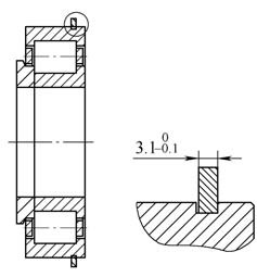
(3) Special bearing puller. Difficulties: When the transmission assembly is disassembled, the auxiliary box bearing and the main shaft two-axis rear bearing are difficult to disassemble. Due to the large load on the entire gearbox, the two bearings have an outer diameter of 175 mm. The existing common pullers cannot be removed, and both bearings have a ring groove structure on the outer ring edge. The only clamping position. As the type of the puller increases, the size of the corresponding parts also increases, and the standard puller jaws are not caught in the ring groove (see Figure 4) and cannot be clamped.

Figure 4
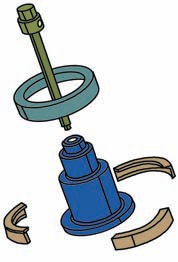
Difficult analysis and solution: Based on this problem, a set of special tooling was designed (see Figure 5). The tooling uses three arc claws, the lower end catches the snap ring groove of the outer ring of the bearing, the upper end catches the cap barrel, and the three arc claws are fixed by the ring sleeve to ensure that the arc claws are not in the drawing process. Scattered. The entire tooling structure is simple and easy to operate, solving the disassembly problem of the two bearings.

Figure 5
(4) Reverse idler shaft detacher. Difficulties: When the transmission assembly is disassembled, the reverse idler and the reverse idler axle are tightly coupled and cannot be disassembled normally. Special tooling is required.
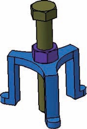
Difficult analysis and solution: According to the thread of the end face of the reverse idler shaft, the appropriate lengthening bolt and nut are used to design and manufacture a triangular bracket to form the disassembler of the reverse idler shaft. It is practical and light, and completely solves the reverse gear. The disassembly of the idler shaft, the specific tooling structure is shown in Figure 6.

Image 6
(5) Design of the bracket for assembling the lock nut. Two lock nuts are assembled on the two-shaft assembly, and the tightening torques are 784 to 1 029 N·m and 539 to 735 N·m, respectively.
How to fix the gear shaft when locking is the key to the problem. To this end, a coupling sleeve is designed. The inner teeth of the coupling sleeve are matched with the two-axis sun gear. The coupling sleeve is mounted on the existing curved plate to form a coupling bracket, and the two-axis assembly is fixed on the coupling bracket. Therefore, the fixing problem of the gear shaft is solved, and as shown in FIG. 7, the assembly of the lock nut is well completed.

Figure 7
4. Conclusion
In the process of assembling the 16TA transmission assembly, a reasonable assembly process was established, and various assembly tools were designed and manufactured to ensure the smooth completion of assembly assembly and provide guarantee for subsequent test verification.


